Overview
This project showcases a two degree-of-freedom gimbal system with independent control over each axis. The primary purpose of this gimbal system is to provide a stable platform for various applications, such as camera stabilization.
Tech Stack
- Softwares: Arduino IDE, Python, Autodesk Fusion 360
- Python libraries: Numpy, Matplotlib, Serial
- Arduino IDE libraries: Adafruit_MPU6050, Adafruit_Sensor, Wire, Servo
Components
| Type | Model | Quantity |
|---|---|---|
| Microcontroller Development Board | Arduino UNO | 1 |
| Inertial Measurement Unit (IMU) | MPU-6050 | 1 |
| Servo Motors | MG996R | 2 |
IMU and Servo Simulation
Using PID, we simulated an IMU and mapped the angle change onto two servos.
We used Wokwi for simulation.
Here, our goal was to simulate the hardware environment before transitioning to the actual hardware components.
Results:
- Smooth changes in servo motor 1 shaft angle in response to IMU-Detected angle variations along the X axis
- Smooth changes in servo motor 2 shaft angle in response to IMU-Detected angle variations along the Y axis
Polar Plot of IMU-Measured Angles
We created a polar plot in Python using the Matplotlib library, based on angle data obtained from the gyroscope within the IMU.
We learned how to establish serial communication between Arduino IDE and Python to import data from an Arduino. This allowed us to plot the changing angle from the IMU as it moves.
Results:
- Serial communication between Arduino IDE and Python without acquiring data from the IMU
- Serial communication between Arduino IDE and Python with acquisition of data from the IMU

Designing the 3-D Model of the Gimbal
We created a 3D model of our gimbal using Autodesk Fusion 360. The model included two axes of rotation and a platform where the mobile phone and IMU were mounted.

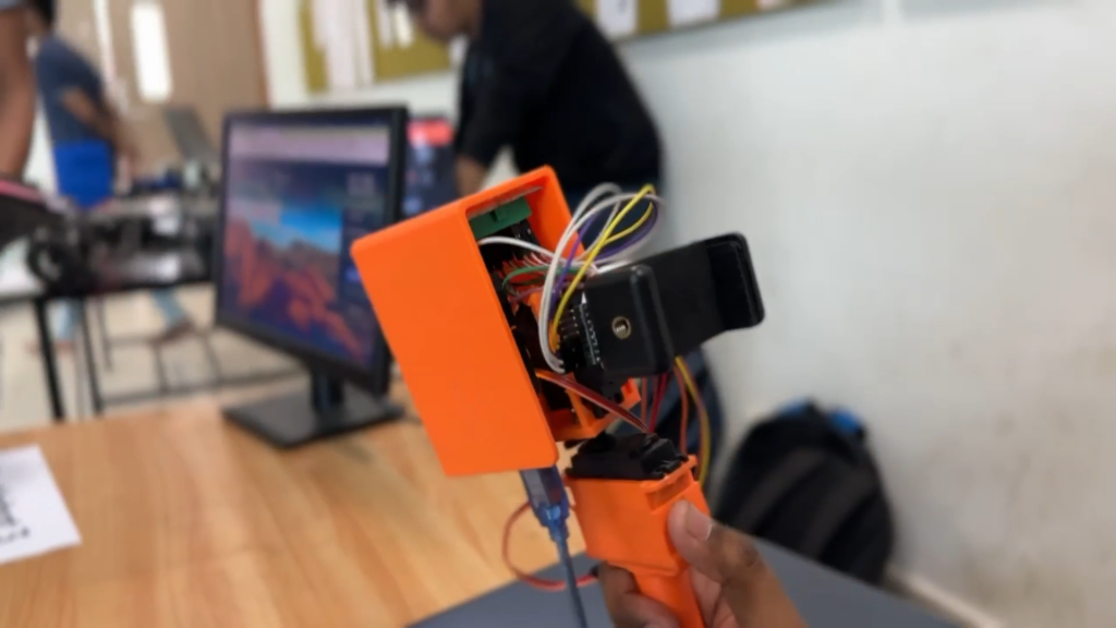
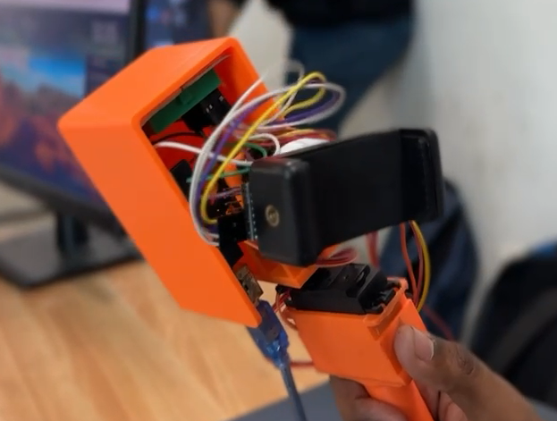
Results
We constructed a prototype using a metal framework to test the algorithm as shown below: