Aim:
To design and develop a fixed-wing Unmanned aerial vehicle. This will involve aerodynamic design, performance analysis using XFLR5, and fabrication of the fixed wing.
DESIGN METHODOLOGY
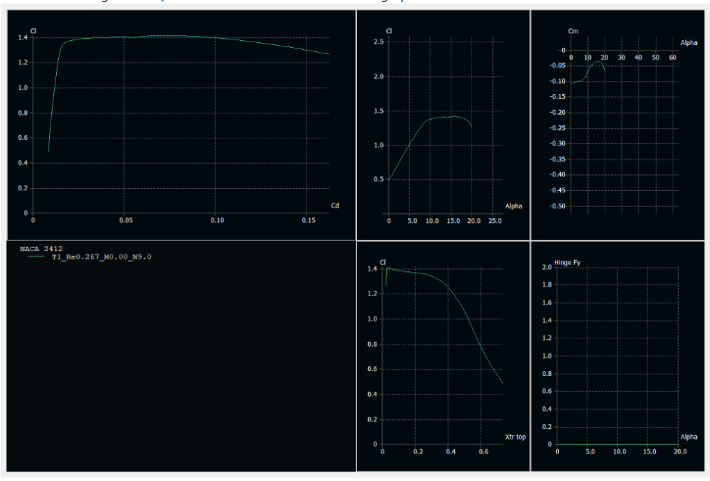
AIRFOIL SELECTION
Airfoil selection is done by selecting different airfoils and then analysing them using XFLR5. We found that NACA2412 with camber 4% gives us Cl=1 at 4 ∘ -5 ∘ AOA. The simulation graphs are shown below. We have designed rectangular wing using this airfoil and elevator, rudder are kept Flat.
WEIGHT ESTIMATION
For estimation of weight, we have found weight of each component individually and then added to get final weight of plane. The estimated weight was found to be 1580 grams. The actual weight of plane (as of now) is 1350 grams.
WING SPAN CALCULATION
For the calculation of wing span We have taken aspect ratio to be 5 which is common for trainers UAV. Then by using the relation of wing loading we found that the wing area to be 3125 cm2 By using the aspect ratio relation we found the length of wing to be 1.25m and chord length of 25 cm.
THRUST TO WEIGHT RATIO
Generally the thrust to weight ratio for a fixed wing plane is kept between 0.5 to 0.7 . For this plane we have consider the thrust to weight ratio to be 0.5 . A thrust-to-weight ratio (TWR) of 0.5 means that the thrust generated by the propulsion system is half the weight of the aircraft.
CONFIGURATION OF AIRCRAFT
Considering the easy of manufacturing, We have considered the following configuration parameters for the plane
- High wing configuration with no dihedral
- Rectangular wing design
- Tractor configuration
CoG ESTIMATION AND ADJUSTMENT
The estimation of centre of gravity is done manually using the fact that the weight of the plane is balanced on the centre of gravity. For adjustment of CoG we adjusted the position of the battery to get the Cog behind the aerodynamic centre of plane i.e
Landing gears
We have used a taildragger configuration of landing gear. The back landing gear is smaller allowing plane’s wing to get required angle of attack during takeoff.
CAD MODEL

A CAD model of aircraft is prepared using this dimensions and fabrication is made with reference to CAD model.
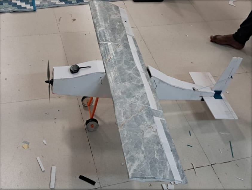
FABRICATION
The fuselag of plane is made using foam sheet cutted into various pieces and then glued together. The wings are made by using styrofoam blocks from which airfoils are made using hot wire cutter in various parts all these parts are combined using Carbon Fibre Rod. The Elevator, Ailerons and Rudder are made using foam sheet. Servos are used to move the control surfaces. The mount for motor, servo connections and landing gears are 3d printed. The Final Fabricated Plane is shown below.