Overview
The objective of this project is to develop a bipedal robot—a two-legged robotic system designed to replicate human gait dynamics. The system focuses on achieving stable locomotion by combining precise limb positioning through Inverse Kinematics (IK) with real-time stability management of the Center of Mass. By integrating control theory with robotic vision and hardware, the robot can simulate and execute balanced walking motions.
Approach
The development followed a modular path, starting from basic control theory and progressing to complex 3D robotic simulation and hardware integration:
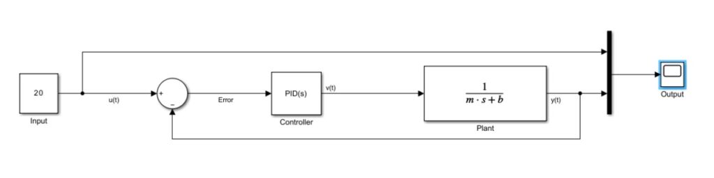
- Control Theory Foundation: We began by developing a Cruise Controller in Python and MATLAB (Simulink) to master PID tuning. This ensured a fundamental understanding of maintaining set-point stability, achieving a rise time of 10 seconds with less than 5% overshoot.
- Kinematic Modeling: We transitioned to robotic manipulators, defining Denavit-Hartenberg (DH) parameters to solve Forward and Inverse Kinematics. Forward Kinematics (FK) was used to determine foot placement based on joint angles, while IK was used to calculate the specific joint angles required to follow a desired spatial path.
- Trajectory Planning: Using Matplotlib and Python, we simulated a 2-DOF manipulator tracing complex paths. We implemented a Sinusoidal trajectory for the “swing” phase of the leg, followed by a straight-line retracement to simulate a realistic walking cycle in the XY plane.
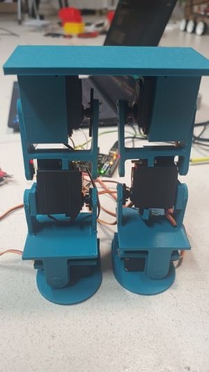
- Hardware Integration: The mathematical models were translated into physical movement using an Arduino UNO and a PCA9685 PWM driver. This allowed for the simultaneous control of 6 servo motors (3 per leg) located at the hip, knee, and foot.
Key Modules
- Kinematics and Trajectory Module: This module handles the mathematical “brain” of the robot. It calculates the necessary angles for the servos to move the foot to a specific coordinate (x, y).
- Inverse Kinematics: The system uses the Law of Cosines to determine joint angles θ1 and θ2 based on the desired foot position and link lengths (a1, a2).
- Path Generation: It generates a sequence of coordinates forming a curve, ensuring the robot lifts its foot high enough to clear the ground while maintaining a smooth velocity profile.
- Control and Stability Module
- PID Control: Adapted from the Cruise Controller task, PID logic is applied to the motor response to ensure smooth transitions between steps without jerky movements.
- Center of Mass Management: By utilizing the ankle (foot) servos, the robot adjusts its tilt to keep its weight centered over the supporting leg during the “single-support” phase of walking.
- Design and Hardware Module
- CAD Modeling: The physical structure was designed in Autodesk Fusion 360, ensuring the 2-DOF legs had the necessary range of motion and structural integrity to support the electronics.
- Electronic Architecture:
- Arduino UNO: Acts as the primary microcontroller.
- PCA9685: Offloads the PWM processing to control 6 high-torque servos with precision and a single I²C interface.
- Servo Array: Distributed as 2 per hip (for lateral and forward movement), 2 for knees, and 2 for feet/ankles.
Summary
The system operates by calculating a rhythmic trajectory for each leg. The Inverse Kinematics engine translates these paths into motor angles, which are then sent from the Arduino to the PCA9685 driver. As the robot moves, the ankle servos compensate for weight shifts to prevent tipping. The result is a synchronized movement where the robot traces a sinusoidal path with its feet, effectively simulating a human-like gait in a controlled environment.
Team Members
- Aniket Kumar Singh
- Dhanvanshi Kumar
- Pakki Dharani Bharadwaj
Mentors
- Aiden D’souza
- Bhuvan Patil
- Manthan Gala
- Yuvraj Gupta