Overview
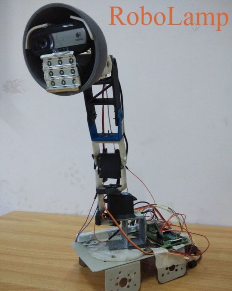
A robo-lamp is a robotic arm with three degree of freedom whose end effector is LED array along with a webcam. The arm is intended to follow the object by performing the necessary movements so that the light is focused at that object.
The video of the object was captured using a webcam and then it was processed with OpenCV. This processes include motion detection, image thresholding and finding the centroid of that particular object. So according to the coordinates acquired (centroid) the arm was supposed to change its position.
Components
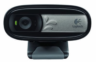
To capture the video
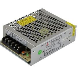
It provides the needed power
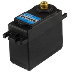
It provides the optimum rotational movement to robotic arm
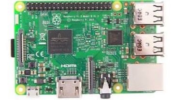
This processes the data and gives the necessary output
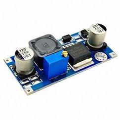
It is used to provide the optimum voltage input to the connected devices
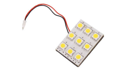
It is used to focus light on object
Softwares


Block Diagram
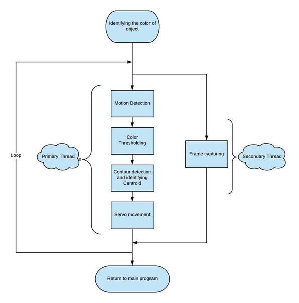
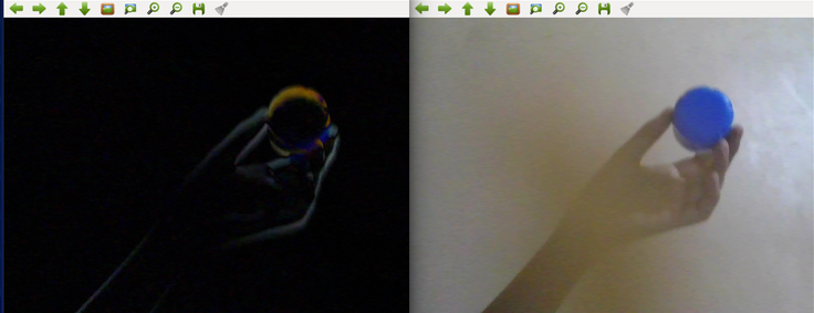
Motion Detection:
When a frame is captured it usually consists of other unnecessary objects in surrounding. Hence there was a need to separate the object(moving) from its surrounding. So the motion detection technique was used which is as followed –
diff = cv2.absdiff(frame1,frame2)
Here frame1 and frame 2 are frames/images captured consecutively.
Color Thresholding:
Once the motion detected image is obtained it needs to be processed further. Here the object was blue colored cap and it needs to be separated from other motion detected surroundings (The Hand and mobile phone in our case). So this object(cap) is blue colored and can be separated by color thresholding as-
ret, thresh = cv2.threshold(diff,127,255,cv2.THRESH_BINARY)
- ret is a boolean variable which gives True or False based on the operation of threshold function
- 127 is the threshold value for Gray scale image.
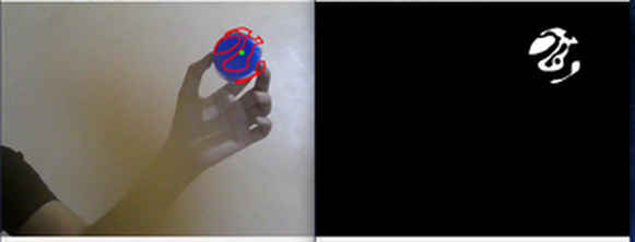
(ii) Gray scale image after thresholding.
Contour Detection and Centroid:
The thresholded image is obtained which can be further processed. First the contours are obtained and then centroid of the largest contour is formulated. The coordinates of the centroid are then used as input for the servo movement code.
Servo Movement:
The coordinates obtained are then compared with the center of screen (reference point). The motion of the servo motors is decided on basis of distance between these two points. An algorithm (derived by trial and error method) is used to convert the distance to angle supposed to rotated by the servo.
Threading:
The code which was written was compiled and tested on Raspberry Pi 3B+(Zero W first). But it was giving a lag of about approx 30 seconds(due to less processing power of Pi processor). This problem was solved by putting the Input Operation of camera in a separate thread since this process took most of the time. As a result Capturing Images as well as processing them is done simultaneously by creating a separate class involving input from cam. Also Raspberry Pi 3B+ was used as it can process multiple threads at the same time. Final lag was about 2 seconds.
Project Video
Members
- Kalpit Jangid
- Tejas Mulay
- Sharan Bajjuri
- Prashil Joshi
Mentors
- Amit Balki
- Sagar Swami